Для владельцев p06 мозгов: с платой 11F0
Набор для переделки во втек мозги (Р28) выглядит так
to convert non-vtec "11F0" boards from non-vtec to vtec, add:
In top left quadrant:
C60 - 1uF, 35v electrolytic (tantalum?) capacitor
J10 - 0 Ohm jumper wire
Q101 - A143 PNP switching transistor
R201 - 10K resistor (Brown-Black-Orange-Gold)
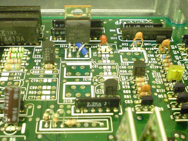
IC14 - 515 XHigh Side Switch MUST USE 5151's OR EQUIVALENT on this board revision. 5050s will throw VTS code.
D11 - Clamping Diode
This is an evolution of the "1720" board design. Things are simpler, as is evidenced by the conversion having fewer components than the 02 D01720-1500 conversion.
Automatic P06 ECUs have SK-5151 high side switches, just in different spots. Desolder them both. Use one for conversion, and save the other one. The A143 transistor (a)Q101 can be taken from Q28 or Q27.
Тут в виде фото:
http://xenocron.com/install/11f0.htm
В разъеме IC14 надо напаять 5151S High Side Switch. Скажу по своему опыту ео достаточно трудно найти,поэтому есть аналоги
http://www.irf.com/product-info/datasheets/data/ir6220.pdf ir6220
http://www.irf.com/product-info/datasheets/data/ips511.pdf ips511
Если возьмете 6220 то вот почитайте эту тему http://forum.pgmfi.org/viewtopic.php?f=2&hilit=ir6210 Тут на фото смотрим распайку ног. Она немного другая.

На всякий случай прикрепил еще на форум фотку + цитата :
I'm prolly the last to find out but I'm gonna post what I found because I see Group buys for SI-5154's when you CAN use a IR6220! I drove to work with an ECU using this method.. The only difference between the IR6220 and SK-5151 becides slight voltage tolerances were Vcc and Vo leads (Pins 3 & 5)..
What I did was stripped a short piece of 10-12ga wire and used the sleeving as a insulator on pin 3 to prevent a short when I crossed leads 3 & 5. Here's pics of the IR6220 installed on a P06, you can even see my makeshift Voltage splitter in "RM11" THANKS GUYS for all the leads...
What I did was stripped a short piece of 10-12ga wire and used the sleeving as a insulator on pin 3 to prevent a short when I crossed leads 3 & 5. Here's pics of the IR6220 installed on a P06, you can even see my makeshift Voltage splitter in "RM11" THANKS GUYS for all the leads...
После этого надо сделать их готовым к чипованию (относиться к любым мозгам P06/P07/P08/P28/P30):
Видео:
http://www.phearable.net/videos/socketing.wmv
Фото:

Распиновка мозгов ОБД1 и ОБД2а/ОБД2б
http://www.hondacivicforum.com/forum/showthread.php?
...to be continued...
Миру - Мир!
Редаговано: MF_Killa (02-03-2012 15:05)


